


Structural modeling of Industrial Building with Bridge Cranes
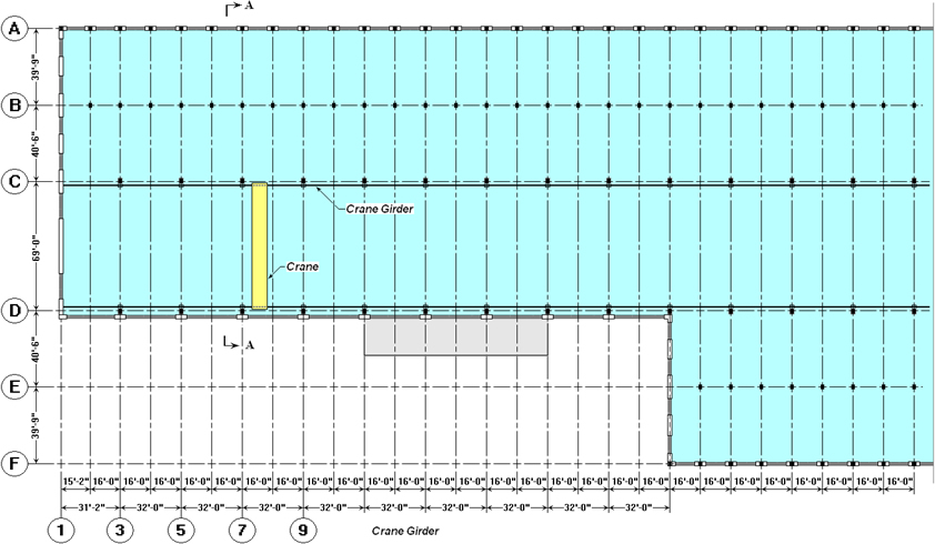
Figure 1 Framing Plan of the Building with Bridge Crane
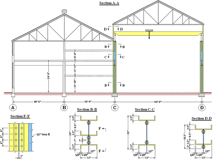
Figure 2 Cross Section of the Building
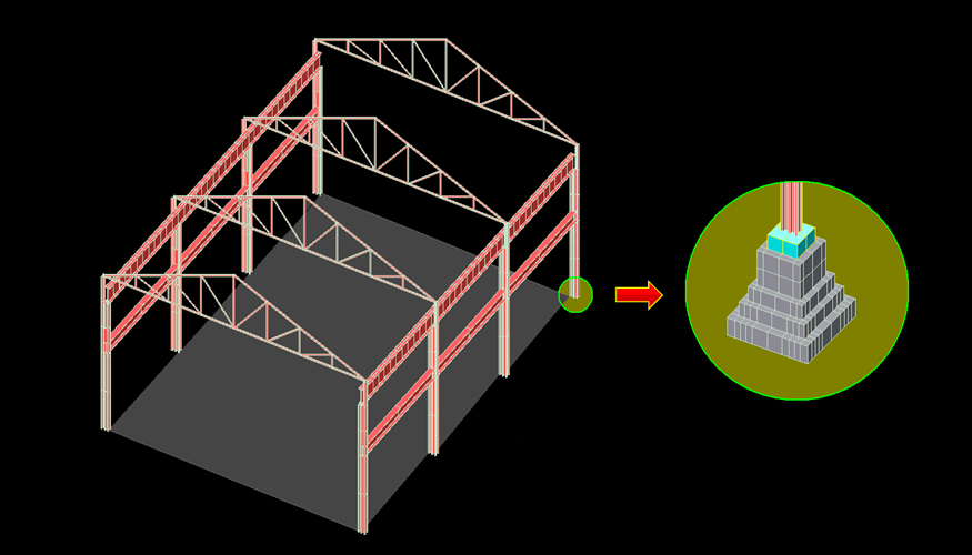
Figure 3 3D FE Model of the Main Span Frame with Extruded View of the Beam Cross Section
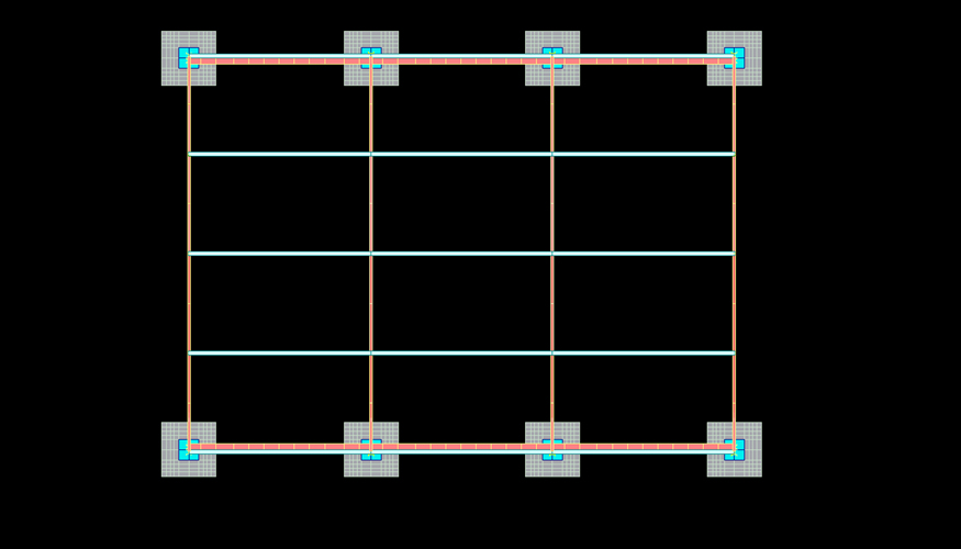
Figure 4 Plane View of the FE Model
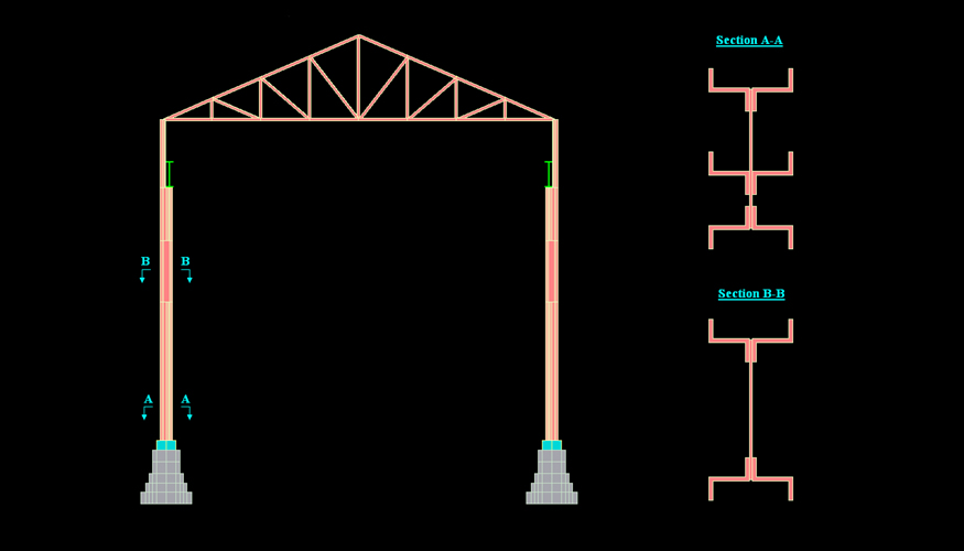
Figure 5 Cross Section of the FE Model
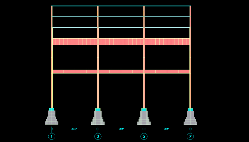
Figure 6 Lateral View of the FE Model
![Figure 7 Stress Contours in Column Structural Elements [DL + (LL+I)]](images/gallery/mbs_1_7.jpg)
Figure 7 Stress Contours in Column Structural Elements [DL + (LL+I)]
![Figure 8 Stress Contours at the Bottom of Concrete Foundation [DL + (LL+I)]](images/gallery/mbs_1_8.jpg)
Figure 8 Stress Contours at the Bottom of Concrete Foundation [DL + (LL+I)]
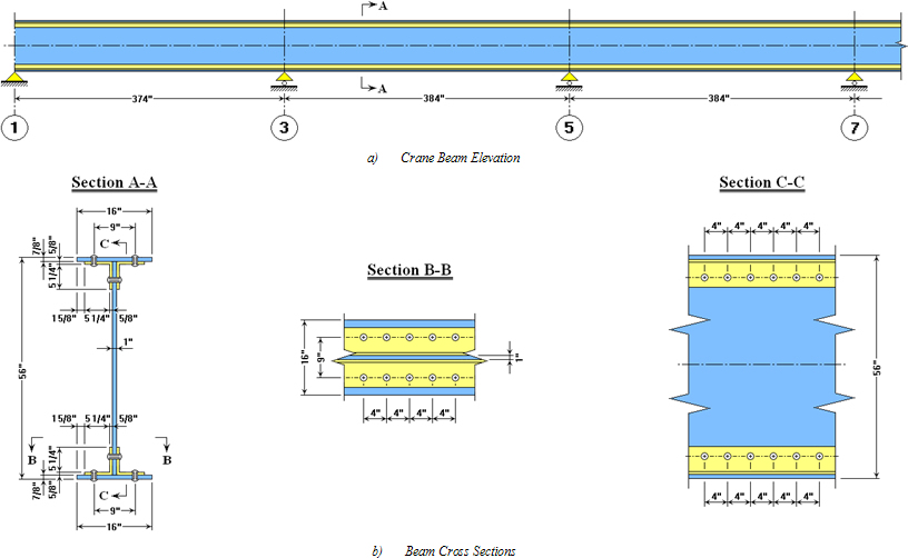
Figure 9 Crane Beam Details
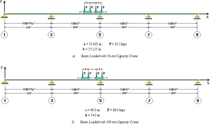
Figure 10 Finite Element Model of the Crane Beam with Different Types of Crane Load
Steel Design Check for Girder Subjected to 50-ton Capacity Crane
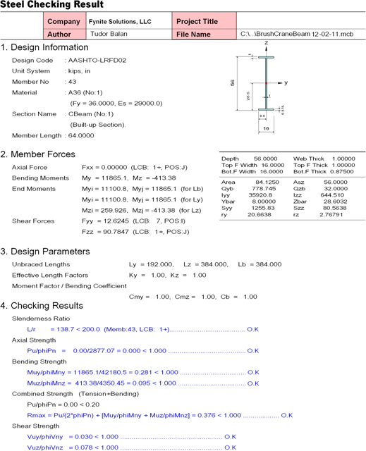
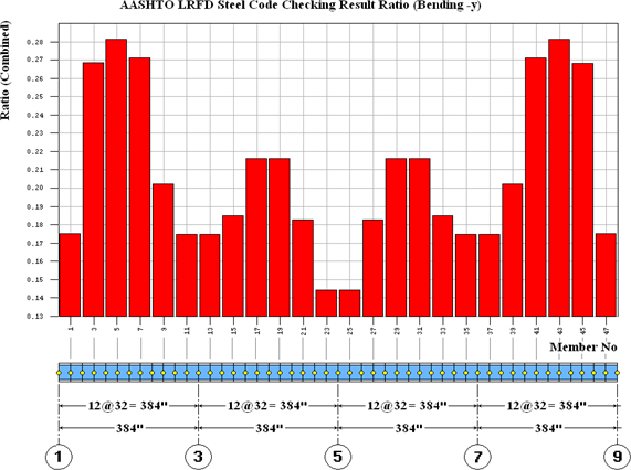
Figure 11 Steel Design Check Results (Utilization Ratio) for Girder under 50-ton Capacity Crane
Steel Design Check for Girder subjected to 100-ton Capacity Crane
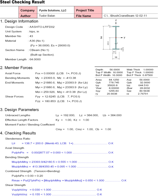
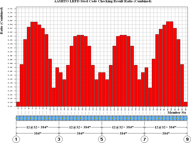
Figure 12 Steel Design Check Results (Utilization Ratio) for Girder under 100-ton Capacity Crane
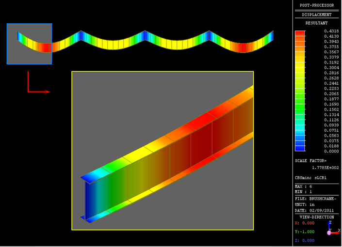
Figure 13 Displacement Contours in Deformed Configuration for Girder beam under 100-ton Capacity Crane
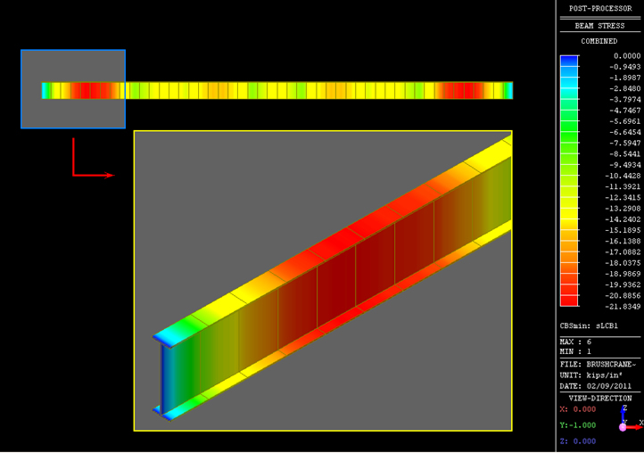
Figure 14 Normal Stress Contours in Girder Beam under 100-ton Capacity Crane
Back to Project Gallery