


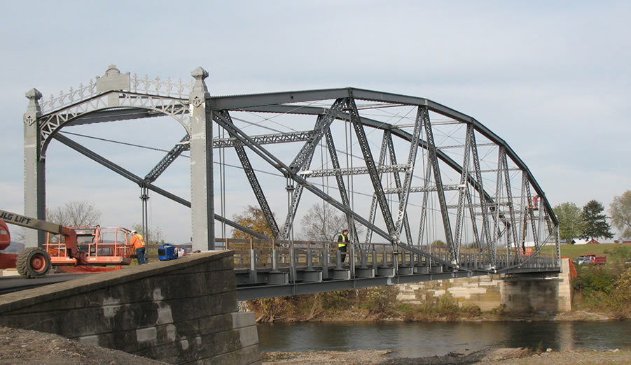
Figure 1 - Pine Creek Lenticular Truss Bridge
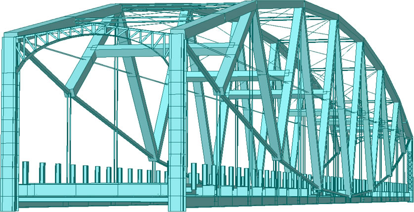
Figure 2 - General View of the Pine Creek Bridge Finite Element Model

Figure 3 - PennDOT Vehicle Used for Moving Load Testing
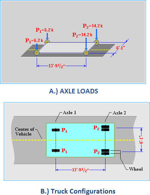
Figure 4 - Vehicular Load Properties
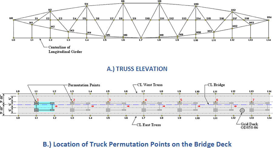
Figure 5 - Vehicular Load Applied as Static Load at Permutation Points 1 to 7 (Moving from Left to Right)
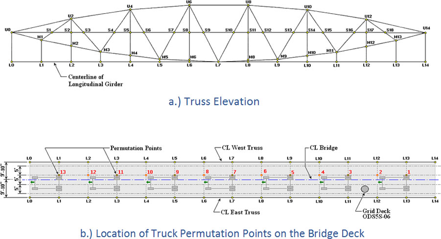
Figure 6 - Vehicular Load Applied as Moving Load at Permutation Points 1 to 7 (Moving from Right to Left at V=15 mph)
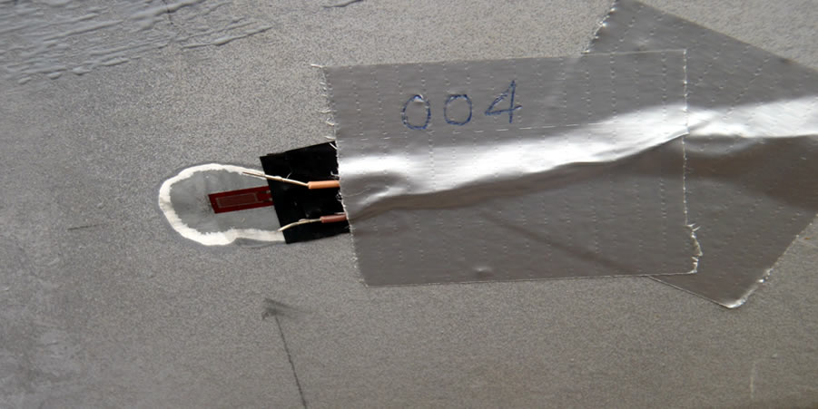
Figure 7 Strain Gage U004 Located on the Bottom Chord of the Truss
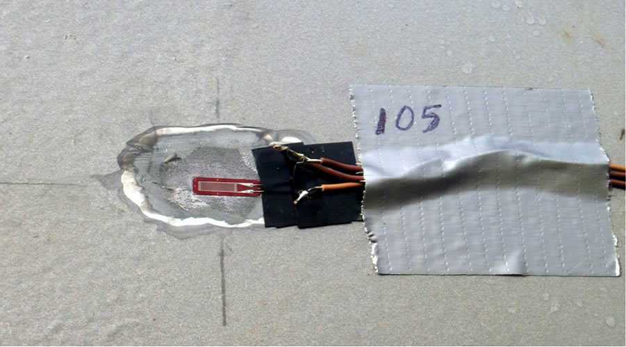
Figure 8 Strain Cage M 1005 Located on the Bottom Chord of the Truss
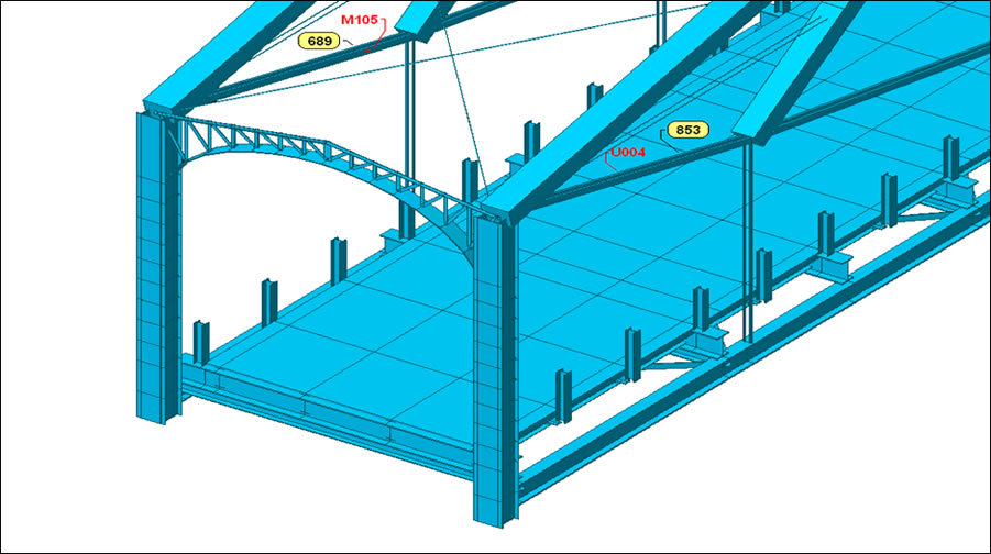
Figure 9 - FE Model with Location of Strain Gages M105 & U004 on FE 689 and 853
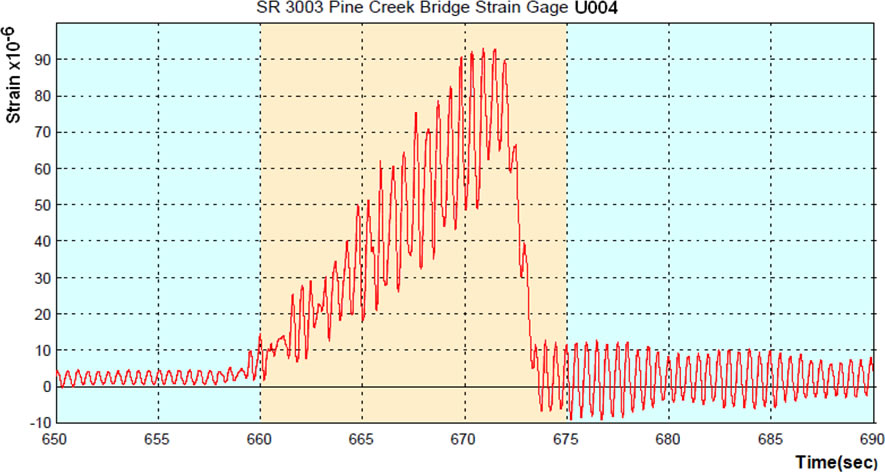
Figure 10 - Recorded Axial Strain Response for Bottom Chord Truss Element 853 (Strain Gage U004)
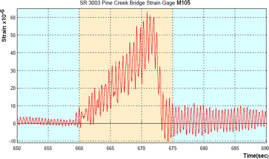
Figure 11 - Recorded Axial Strain Response for Bottom Chord Truss Element 689 (Strain Gage M105)
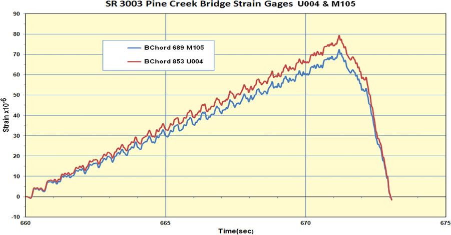
Figure 12 - FE Time-History Analysis Predicted Axial Strain Response for Bottom Chord Truss Elements 853 and 689 (Strain Gages U004 & M105)

Figure 13 - Strain Gages M106 and M111 Located on vertical Rods
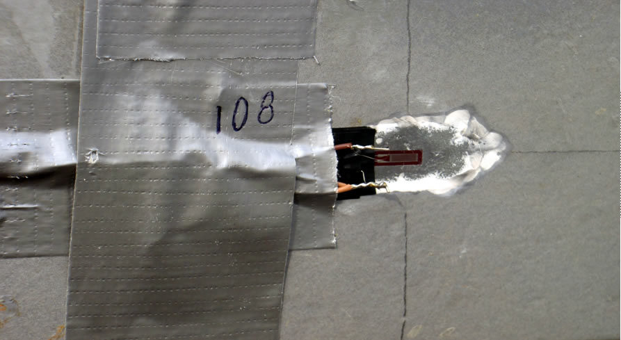
Figure 14 Strain Gages M108 Located on Bottom Chord of the Truss
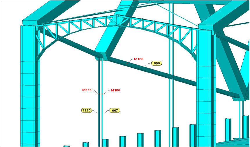
Figure 15 - FE Model with Location of Strain Gages M106, M108 and M111(FE 667, 690 and 122)
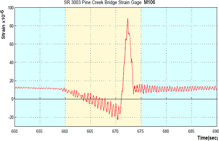
Figure 16 - Recorded Axial Strain Response for Hanger Truss Element 667 (Strain Gage M106)
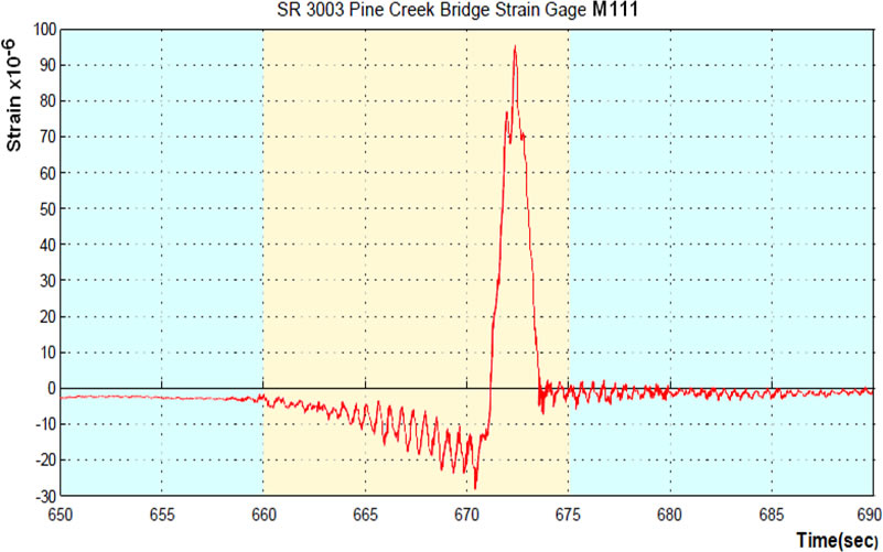
Figure 17 - Recorded Axial Strain Response for Hanger Truss Element 1225 (Strain Gage M111)
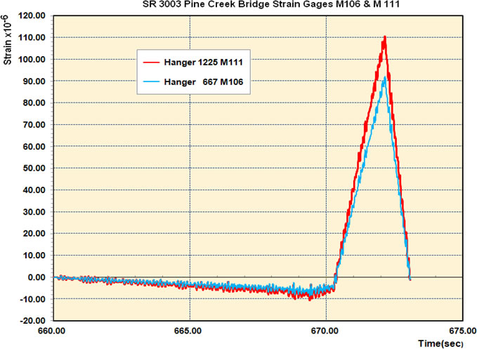
Figure 18 FE Time-History Analysis Predicted Axial Strain Response for Hanger Truss Elements 667 and 1225 (Strain Gages M106 & M111)
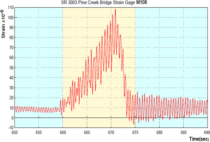
Figure 19 - Recorded Axial Strain Response for Bottom Chord Truss Element 690 (Strain Gage M108)
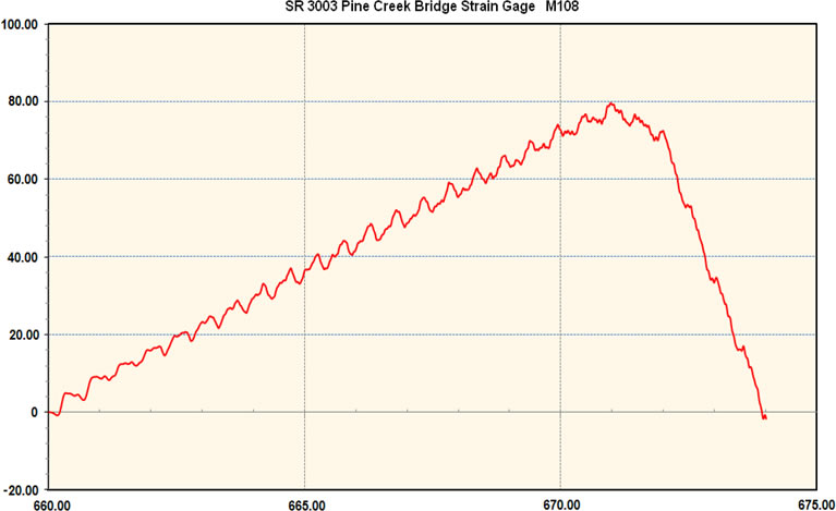
Figure 20 - FE Time-History Analysis Predicted Axial Strain Response for Hanger Truss Elements 690 and 1225 (Strain Gage M108)
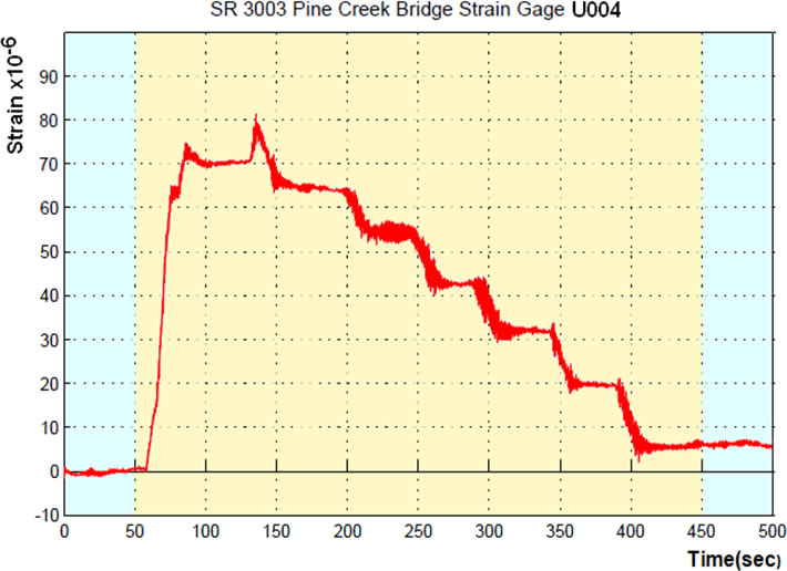
Figure 21 - Test Axial Strain Response for Bottom Chord Truss Elements 689 and 853 (Strain Gages M105 & U004)
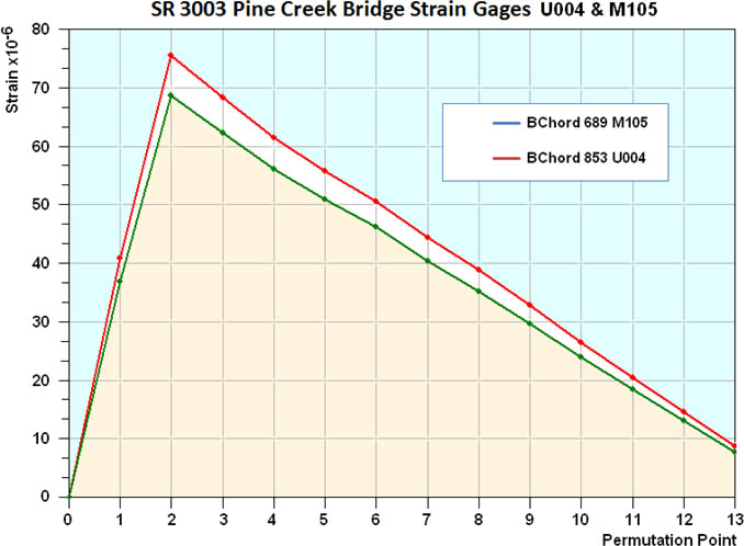
Figure 22 - FE Stage Analysis Predicted Axial Strain Response for Bottom Chord Truss Elements 689 and 853 (Strain Gages M105 & U004)
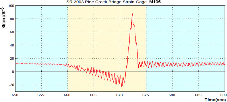
Figure 23 - Test Axial Strain Response for Bottom Chord Truss Element 690 (Strain Gage M108)
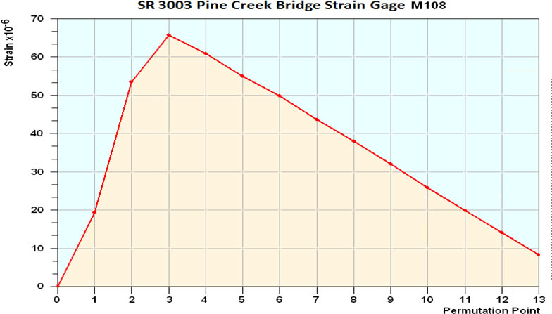
Figure 24 - FE Stage Analysis Predicted Axial Strain Response for Bottom Chord Truss Element 690 (Strain Gage M108)
Back to Project Gallery